LTspice printer-friendly settings
Printer-friendly charts
By default LTspice uses a set of colors suited only for displaying on a computer screen, but with a couple of problems:
- The charts using the default color-theme do not scale nicely, because of the low contrast (ex: green lines on black background)
- The charts are not suited for printing (black backgrounds).
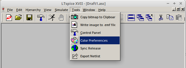
Fortunately, the colors can be changed easily. From the “Tools” menu pick “Color preferences”.
From the “Color palette editor” pick the “WaveForm” tab.
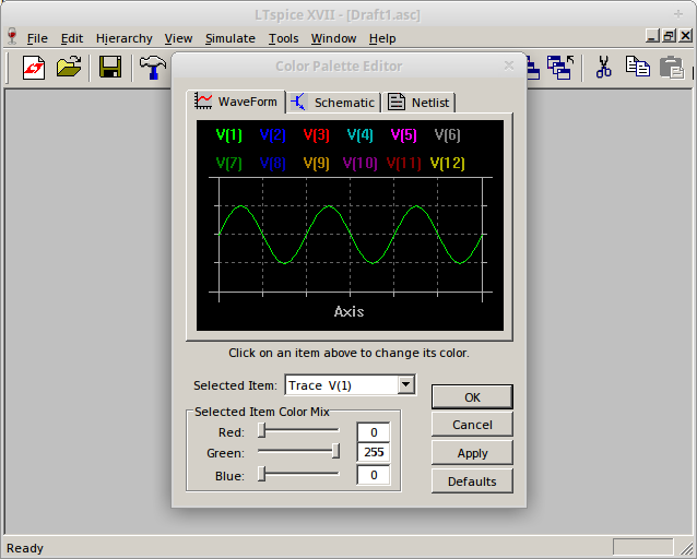
For every “Selected Item” from the table below we set the colors:
| Item | Red | Green | Blue |
|---|---|---|---|
| Background | 255 | 255 | 255 |
| Grid | 0 | 0 | 0 |
| Axis | 0 | 0 | 0 |
| Inactive axis | 0 | 0 | 0 |
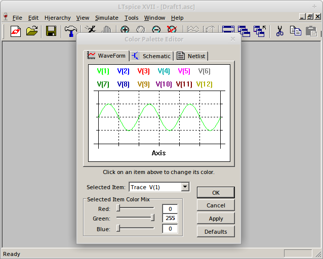
Now the “Preview” area should look like this:
Printer-friendly schematics
Using the same steps as above, go to the “Color Palette Editor”.
From here configure the following items:
| Item | Red | Green | Blue |
|---|---|---|---|
| Wires | 0 | 0 | 0 |
| Junctions | 0 | 0 | 0 |
| Component body | 0 | 0 | 0 |
| Graphic flag | 0 | 0 | 0 |
| Unconnected pin | 0 | 0 | 0 |
| Background | 255 | 255 | 255 |
Labeled blocks inside schematics
From the menus, we choose:
Edit ⇨ Draw ⇨ Rectangle, do draw a rectangle;Edit ⇨ Text, do add a text comment.
With these, we split larger circuits into blocks, and label these blocks. The text comments are ignored by the simulation engine, being useful only for the end-users.
Labeled nets
We can tie together two points on the schematic without drawing a wire between them. If two points on the schematics are labeled with the same “net” name, the simulation backend considers them as being the same. Another useful detail is that on the chart resulting from the simulation, the traces are labeled with their net name.
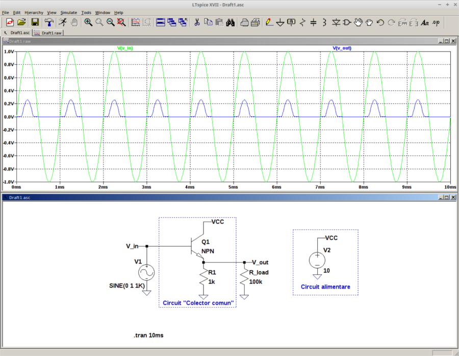
Example
We can observe the following details:
- V_in and V_out are labeled on both the schematic and the simulation trace;
- The functional blocks of the schematic are highlighted and labeled clearly;
- The amplifier circuit (on the left) is powered by the power-supply block (on the right) without any explicitly-drawn wire - VCC is connected using the net label, and GND is connected using a symbol.
Shortcuts
| Keyboard shortcut | Role |
|---|---|
| F2 | Add component |
| F3 | Add wire |
| F4 | Add label |
| F9 | Undo |
| G | Add GND connection |
| R | Add resistor |
| C | Add capacitor |
| L | Add inductor |
| Ctrl+R | Rotate |
| Ctrl+E | Mirror |